NMS100-LS Leak Alarm Module (Location)
Legal Notices
Before installing and using the product, please read the installation manual.
Please keep this manual in a safe place so that you can refer to it at any time in the future.
NMS100-LS
Leak Alarm Module (Location) User Manual
(Ver1.0 2023)
About this product
The products described in this manual can only be granted after-sales service and maintenance programs in the country or region where they are purchased.
About this manual
This manual is only used as a guide for related products, and may be different from the actual product, please refer to the actual product. Due to product version upgrades or other needs, the company may update this manual. If you need the latest version of the manual, please log on to the company's official website to view it.
It is recommended that you use this manual under the guidance of professionals.
Trademark Statement
Other trademarks involved in this manual are owned by their respective owners.
Responsibility statement
To the maximum extent permitted by law, this manual and the described products (including its hardware, software, firmware, etc.) are provided "as is" and there may be defects or errors. The company does not provide any form of express or implied guarantee, including but not limited to merchantability, quality satisfaction, fitness for a specific purpose, etc.; nor is it responsible for any special, incidental, accidental or Compensation for indirect damages, including but not limited to loss of commercial profits, system failure, and system misreporting.
When using this product, please strictly follow the applicable laws and regulations to avoid infringing the rights of third parties, including but not limited to publicity rights, intellectual property rights, data rights or other privacy rights. You also may not use this product for weapons of mass destruction, chemical or biological weapons, nuclear explosions, or any unsafe use of nuclear energy or human rights violations.
If the content of this manual conflicts with applicable laws, the legal provisions shall prevail.
Safety Instructions
The module is an electronic device, and some precautionary measures should be strictly followed when using it to avoid equipment damage and personal injury and other safety accidents.
Do not touch the module with wet hands.
Do not disassemble or modify the module.
Avoid contacting the module with other pollutants such as metal shavings, grease paint, etc.
Please use the equipment under the rated voltage and rated current to avoid short circuit, burning and safety accidents caused by abnormal conditions.
Installation Precautions
Do not install it in a place prone to dripping or immersion.
Do not install in an environment with excessive dust.
Do not install it where strong electromagnetic induction occurs.
When using the module output contacts, please pay attention to the rated capacity of the output contacts.
Before installing the equipment, please confirm the rated voltage and power supply of the equipment.
The installation location should avoid high temperature and high humidity, vibration, corrosive gas environment and other sources of electronic noise interference.
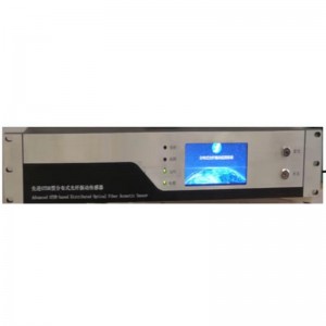
Product Introduction

✓ High reliability
✓ 1500 meter leak detection support
✓ Open circuit alarm
✓ Location display by LCD
✓ Telecommunication protocol: MODBUS-RTU
✓ Relay output on site
NMS100-LS leak alarm module functions on real monitor and detect once leakage occurs, it supports 1500 meter detection. Once leakage is detected by sensing cable, NMS100-LS leak alarm module shall trigger alarm through relay output. It is featured with alarm location LCD display.
NMS100-LS supports RS-485 telecom interface, integrating with a variety of monitoring systems via MODBUS-RTU protocol to realise remote monitor of the leakage.
Applications
Building
Datacenter
Library
Museum
Warehouse
IDC PC room
Functions
◆High reliability
NMS100-LS module is designd base on industrial electronics level, with high sensitivity and less false alarm caused by diversified external factors. It is featured with anti-surge, anti-static, and anti-FET protection.
◆Long distance detection
NMS100-LS leak alarm module could detect water, electrolyte leakage from 1500 meter sensing cable connection, and alarm location is shown on LCD display.
◆Functional
NMS100-LS leak alarm and open circuit alarm are shown through LED on NMS100-LS module to illustrate its working condition.
◆Flexible Usage
NMS100-LS not only can be applied as an alarm unit seperately, but also can be integrated into network application. It shall communciate with other monitor systems/platforms, or host computer through communication protocol to realise remote alarm and monitor.
◆Easy Configuration
NMS100-LS has its software allocated address, RS-485 could support upto 1200 meter.
NMS100-LS is configured by its software for a variety of leakage detection applicaitons.
◆Easy installation
Applied for DIN35 rail installation.
Technical Protocol
| Sensing technology
|
Detection Distance | Upto 1500 meter |
| Response Time | ≤8s | |
| Detection Precision | 1m±2% | |
| Communication Protocol | Hardware Interface | RS-485 |
| Communication Protocol | MODBUS-RTU | |
| Data Parameter | 9600bps,N,8,1 | |
| Address | 1-254 (default address: 1出厂默认1) | |
| Relay Output | Contact Type | Dry contact, 2 groups Fault:NC Alarm:NO |
| Load Capacity | 250VAC/100mA、24VDC/500mA | |
| Power Parameter | Rated Operating Volume | 24VDC,voltage range 16VDC-28VDC |
| Power Consumption | <0.3W | |
| Working Environment
|
Working Temperature | -20℃-50℃ |
| Working Humidity | 0-95%RH (non-condensing) | |
| Leak Alarm Module installation | Outlook Size | L70mm*W86mm*H58mm |
| Color and Material | White, anti-flame ABS | |
| Installation Method | DIN35 rail |
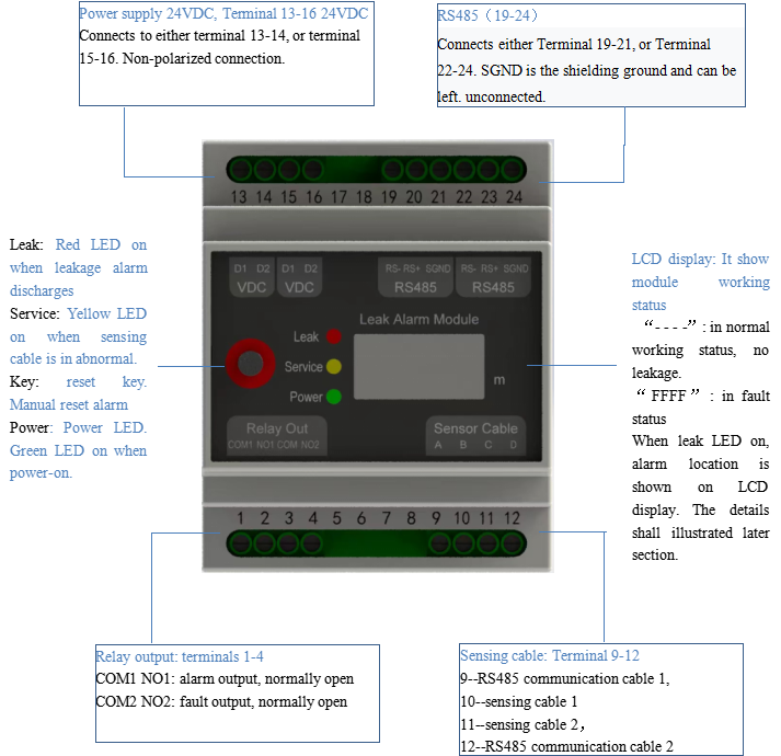
Indicator Lights, Keys, and Interfaces
Remarks:
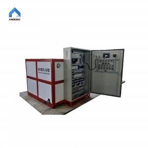
(1)Leak alarm module is not anti-water designed. Anti-water cabinet need to prepare in special cases.
(2)Leak alarm location, as displayed, is according to the sensing cable starting sequence, but leader cable length is not included.
(3)Relay output can not connect directly to high electric current /high voltage power supply. Relay contacts capacity for extension is required if need, otherwise NMS100-LS shall be distroyed.
(4)Leak alarm module supports upto 1500 meter(leader cable length and jumper cable length are not included )。
Instalaltion Instruction
1.Leak detection module shall be placed indoor computer cabinet or module cabinet for easy maintainance, with DIN35 rail installation.

Picture 1 - rail installation
2.Leak sensing cable installation should keep far away from high temperature, high humidity, excessive dust, and strong electromagnetic induction. Avoid the sensing cable outer shealth broken.
Wiring Instruction
1.RS485 cable:Shielded twisted pair communication cable is suggested. Please pay attention to the positive and negative polarity of the interface when wiring. Communication cable shielding grounding is suggested in strong electromagnetic induction.
2.Leak sensing cable:It is not suggested have the module and the sensing cable connected directly in order to avoid wrong connection. Instead, leader cable (with connectors) is suggest to apply in-between, and that is the right cable (with connector) we could supply.
3.Relay output:Relay output can not connect directly with high electric current/ high voltage equipment. Please properly apply as required under the rated relay output capacity. Here are relay output status shown as below:
| Wiring | Alarm (leak) | Relay Output Status |
| Group 1: leak alarm ouput
COM1 NO1 |
Leak | Close |
| No Leak | Open | |
| Power off | Open | |
| Group 2: fault output
COM2 NO2 |
Fault | Open |
| No Fault | Close | |
| Power off | Open |
System Connection
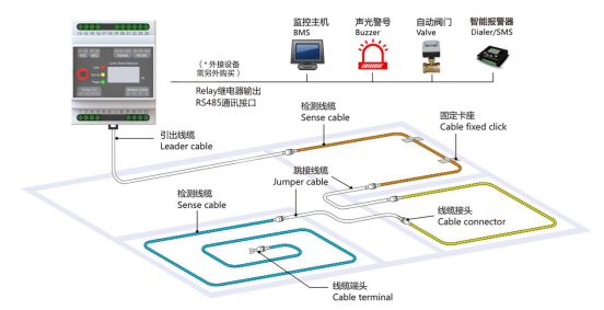
Through NMS100-LS alarm module and leak detection sensing cable connection, alarm shall discharge in terms of alarm relay output once leakage is detected by the sensing cable. Signal of alarm and alarm location is transmitted via RS485 to BMS. The alarm relay output shall direct or indirect trigger buzzer and valve etc.
Debug Instruction
Debug after wire connection. The below is debug procedure:
1.Power on leak alarm module. Green LED On.
2.The below, as shown in Picture 1, illustrates normal working condition --- correct wiring, and no leakage/no fault.
Picture 1. in normal working condition
3.The below, as shown in Picture 2, illustrates wrong wiring connection or short circuit on the sensing cable . In this case, yellow LED on, suggest check wiring status.

Picture 2: Fault Status
4.Under normal working condition, leak sensing cable is immersed into water (unpurified water) for a while, e.g. 5-8 seconds before alarm is discharged: Red LED on in terms of relay alarm output. Alarm location display on LCD, as shown Picture 3.

Picture 3:Alarm Status
5.Take leak sensing cabe out from water, and press reset key on leak alarm module. In case that alarm module is in network, Reset shall be managed through PC commands, referred to section Communication Reset Commands, otherwise alarm shall be remained.

Picture 4: Reset
Communication Protocol
Communication Introduction
MODBUS-RTU, as a standard communication protocol, is applied. Physicial interface is two-wired RS485. Data reading interval is not less than 500ms, and the recommended interval is 1s.
Communication Parameter
|
Transimission Speed |
9600bps |
|
Transimission Format |
8,N,1 |
|
Device Default Address |
0x01 (factory default, edited on host computer) |
|
Physical Interface |
Two-wired RS485 interface |
Communication Protocol
1.Send Command Format
| Slave number | Function number | Data Start Address (High + Low) | Number of Data (High + Low) | CRC16 | ||
| 1bype | 1bype | 1bype | 1bype | 1bype | 1bype | 1bype |
2.Answer Command Format
| Slave number | Function number | Data Start Address (High + Low) | Number of Data (High + Low) | CRC16 | ||
| 1bype | 1bype | 1bype | 1bype | 1bype | 1bype | 2bype |
3.Protocol Data
| Function Number | Data Address | Data | Illustration |
| 0x04 | 0x0000 | 1 | Slave number 1-255 |
| 0x0001 | 1 | Cable unit resistance (x10) | |
| 0x0002 | 1 | Leak alarm module 1- normal, 2- open circuit, 3- leakage | |
| 0x0003 | 1 | Alarm location, no leakage: 0xFFFF (unit - meter) | |
| 0x0004 | 1 | resistance from sensing cable length | |
| 0x06 | 0x0000 | 1 | Configure slave number 1-255 |
| 0x0001 | 1 | Configure sensing cable resistance (x10) | |
| 0x0010 | 1 | Reset after alarm (send “1” for reset, not valid in condition of non-alarm status. ) |